|
ARM Cortex-M3 Interrupts
2013-11-26 Piotr Romaniuk, Ph.D.
Contents
NVIC - Nested Interrupt Controller
Impression of the Mess in Naming
Exceptions, Faults and Interrupts
Exception Vector Table
Exception States
Interrupt Priorities
Exceptions Order
Masking (blocking) Exceptions
Hardware Registers Stacking on Exception
Tail-chaining
Late arriving interrupt
Processor Pipeline and Interrupts
Links to External Information on ARM-Cortex-M3 Interrupts
NVIC - Nested Interrupt Controller in Cortex-M3
ARMv7-M core is equipped with interrupt controller NVIC [Nested Vectored Interrupt Controller]. NVIC allows for 496 independent interrupts.
The controller can be triggered by level on edge on its input line. NVIC uses exceptions (i.e. generalization of interrupt term) vector table and
advanced mechanism for priorities. The priorities can be configured in various way providing flexible control over mutual preemption and their importance.
Cortex-M3 core has additional hardware extensions that supports interrupts, i.e. stacking registers on interrupt entry, optimization in nesting case, etc.
Impression of the Mess in Naming
Let's focus on examplar microcontroller from ST Microelectronics - STM32L. There seems to be a mess in naming, one can wonder how following names are related:
ARMv7-M, Cortex-M3, STM32L ?
I'am just explaining: ARMv7-M is an architecture type, its implementation is Cortex-M3 and STM32L is a type of microcontroller (a family)
that has Cortexa-M3 core inside (among the core, the chip contains many interfaces, timers, FLASH memory, etc.).
Exceptions, Faults and Interrupts
In specification of ARMv7-M core following names can be found:
- Exceptions - it is general term for others,
- Faults - critical errors of the core,
- Interrupts - external interrups.
The exception can be raised because of:
- intentional (present in code) execution of the instruction, e.g. SVC #n
- as a result of the system behavior
- when hardware interrupt appears
- breaking memory protection rules
- bus or alignment errors
- errors of core state
- debug events
It must be taken into consideration that ARMv7-M core differs from ARMv7 in servicing interrupts because of following items:
- performs hardware stacking the registers on ISR entry (on exit it restores the registers from stack)
- uses vector table of functions for exceptions handling
- exception are groupped in different way
Exceptions Vector Table
Exceptions Vector Table consists of word (32 bits) size items. The first item is an initial value of stack pointer register (SP) used after reset.
Consecutive elements in the table are filled with addresses of exception handling functions.
The addresses must have set bit0 that is interpetted by the core as a request for Thumb mode on ISR entry.
If the bit is not set, this results UsageFault exception and HardFault exception for reset handler.
Exception State
Exceptions can be in following states:
- pending - exception is already raised but is not yet serviced by the core
- active - the core started servicing this exception but does not finished yet. Exception in this state can be preempted by
another exception with higher priority.
- inactive - when exception is not in active nor pending state
Asynchronous exception (e.g. external interrupts) can be simultanously in active and pending state at the same time.
This property provides that the exception is not lost if it is raised during execution of its ISR.
Dzięki temu np. nie zostanie zgubione przerwanie zgłoszone podczas jego obsługi.
Priorytety przerwań
ARMv7-M uses complex priority mechanism for exceptions ordering.
The first three, most critical exceptions (i.e. Reset, NMI, HardFault) have fixed priorities -3, -2, -1, correspondingly. Priorities of other exceptions can be configured and changed.
Each configurable priority consists of two parts (bit fields):
1. preemption group
2. sub-priority
The value of priority is no more than 8-bits wide (NOTE: STM32L has 4-bits wide priorities).
Two parts of the priority provides control over exception preemption. When the core need to decide which exception should be handled first it follows the rules:
- priority with smaller value is more important
- exception can be preempted only by other exception from more important preemption group,
- if two interrupts are from the same preemption group, first handled is the one with more important subpriority (i.e. lower value)
- if two exceptions have the same priorities, first handled is the one with lower number (is located in exception table closer to begin of the table) -
these numbers are fixed
- all configurable exceptions has priority 0
Before you start to assign priorities, you need to decide how to split n-bits priority into two parts.
For example STM32L can be configured as follows:
| Case | Split | number of preemption groups | number of sub-priorities in the group | notes |
| 1. | 0:4 | 1 | 16 | no preemption |
| 2. | 1:3 | 2 | 8 | |
| 3. | 2:2 | 4 | 4 | |
| 4. | 3:1 | 8 | 2 | |
| 5. | 4:0 | 16 | 1 | each exception can be preempted |
Required rules of preemption can be implemented by proper assigning exceptions to the groups and setting sup-priorities.
Example
Some embedded system based on STM32L uses 3 interrupts: EXTI0 (from external GPIO pin), USART1 (from USART, received/sent character) and TIM9 (Timer Interrupt).
The requirement is that the exceptions from timer and usart should not preempt each other, and if are both pending usart interrupt should be handled first.
We want that GPIO interrupt should has the highest priority and should preempt two former exceptions.
In order to satisfy these rules, the exception priorities can be configured as below:
* split the priority into group:sub-priority: 2:2
* priority EXTI0: 0.0 = 0
* priority USART1: 1.0 = 4
* priority TIM9: 1.1 = 5
Exceptions Order
An order of exceptions has two meanings:
- it defines which one is more important when two exceptions has the same priority
- defines exception location in exception vector table
Below you may find some part of exception list for STM32L1xx small and medium density devices
| Priority | Nama | Description | Address | notes |
| -3 | Reset | Reset | 0x0000.0004 | fixed priority |
| -2 | NMI | non maskable interrupt | 0x0000.0008 | fixed priority |
| -1 | HardFault | critical core errors | 0x0000.000c | fixed priority |
| 0 | MemManage | memory manager | 0x0000.0010 | |
| 1 | BusFault | fault at prefetch or memory access | 0x0000.0014 | |
| 2 | UsageFault | undefined opcode or incorrect state | 0x0000.0018 | |
| 3 | SVC_Handler | system service call by SVC | 0x0000.002c | |
| 4 | DebugMon | debug monitor | 0x0000.0030 | |
| 5 | PendSV | request for pending system call | 0x0000.0038 | |
| 6 | SysTick | system timer - periodic interrupt | 0x0000.003c | |
| 7 | WWDG | Window watchdog | 0x0000.0040 | |
| .. | ... | ... | 0x0000.0044 | |
| 13 | EXTI0 | interrupt from GPIO pin | 0x0000.0058 | |
| .. | ... | ... | 0x0000.005c | |
| 17 | EXTI4 | interrupt from GPIO pin | 0x0000.0068 | |
| 18 | DMA1_Channel1 | DMA1 channel 1 | 0x0000.006c | |
| .. | ... | ... | 0x0000.0070 | |
Exceptions that comes from the core (Cortex-M3) are located at the begining of above list - they are highlighted in the table by darker color.
According to naming in ARMv7-M documentation, PendSV and SysTick are external interrupts for the core.
NOTE: CMSIS library uses another numbering: IRQn <0 - processor exceptions, IRQn >= 0 - external exceptions (external for to the core).
Masking (blocking) Exceptions
Exceptions can be masked on different level:
* globaly by setting a flag in registers PRIMASK and FAULTMASK (CPSIE/D i/f)
* by limiting alowed priority - BASEPRI register (precisely: by specification preemption group)
* by setting proper mask bit in interrupt controller
Setting BASEPRI=0 disables limitation. Setting positive value makes blocked exceptions with priority value higher or equal to value BASEPRI register.
NOTE: BASEPRI blocks on the level of preemption groups (but not sub-priorities).
Hardware Registers Stacking on Exception
After the exception is raised, the Cortex-M3 core does in parallel two operations: (1) fetches a vector from exception vector table and (2) pushes main registers on the stack(i.e. r0-r3, r12, LR, PC, xPSR).
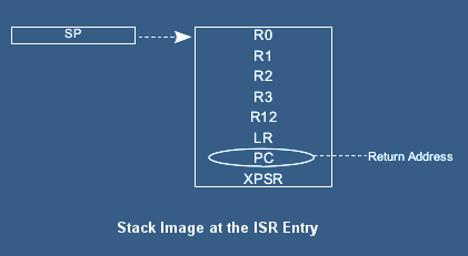
When the ISR is finished registers are automatically restored from the stack.
Tail-chaining
In order to optimize handling two sequential interrupts designers of Cortex-M3 introduced Tail-Chaining. When some interrupt is pending
at the time of finishing ISR, registers are not recovered from stack and pushed again but execution is instantly directed to next ISR.
Late arriving interrupt
In order to optimize interrupt latency and interrupt preemption, Cortex-M3 can preempt current interrupt just before it enters ISR.
For example: some low priority interrupt has pushed registers on the stack but not started its IRS. At this moment preempting interrupt appears.
In this case the core swithes to the arriving, high priority interrupt. This mechanism is described in documentation as 'Late-Arriving-Interrupt'.
Processor Pipeline and Interrupts
Processor Cortex-M3 has a pipeline with 3 stages: for fetching, decoding and executing instructions respectively.
Because of that result of some instructions are not effective (i.e. visible) for consecutive instruction. For example, interrupts are not enabled yet
for next instruction after CPSIE i. Of cource, this is not the only case.
If this is not required or makes trouble, proper barrier instruction should be used.
The barriers assure that pipeline is flushed or the result has been stored in the memory, so result can be observed by the next instruction after barrier.
Cortex-M3 has following types of barriers:
DMB - Data Memory Barrier
DSB - Data Synchronization Barrier
ISB - Instruction Synchronization Barrier
Links to External Information on ARM-Cortex-M3 Interrupts
- ARM Information Center,
- ARMv7-M Architecture Reference Manual,
- Cortex-M3 Technical Reference Manual,
- STM32L1xx Reference Manual
|
