More about ELESOFTROM Company

ELESOFTROM Company is specializing in firmware development and fixing for embedded systems.

We have more than 10-years of experience in that area.

In developed tasks and projects we value reliability and effectivness of the firmware.

Fixing the Software for Emebedded Systems

Software for Microcontrollers


Home page

Full offer

Experience

About company

Contact


DioneOS - RTOS for embedded devices

ELESOFTROM developed RTOS for ARM Cortex-M3 and msp430.

The system is optimized for short execution time, having short switching time between threads.
The system provides elements (e.g. semaphores, mutexes, timers, queues etc.) used for building multi-threaded firmware.

Cortex version has full tests coverage and was tested by automatic testing framework.

Read more:

DioneOS home page

Reliability

Performance

DioneOS documentation

Tutorials about DioneOS


State Machines - Description of System Behavior

2013-11-27    Piotr Romaniuk, Ph.D.

Contents

Description of System Behavior
State Machine
Naive Implementation of the System Behavior (DO NOT DO THIS WAY!)
How to Create a Model of the System Behavior in State Machine Form
Simple Implementation of State Machine
State Machine - Better Implementation
More State Machines
Definition Different Types of the Machines
Separation the Definition and Usage (Framework, Library)
State Machine Manager and State Machine as Active Object
Code Generators and Translators
Links

Description of System Behavior

Let's consider a system which behavior depends on its past - it has some kind of a memory. In its history its state changes on input events and in each state the system can respond in various ways for the same inputs. Indirectly this description has been just focused on discrete systems. In a case of embedded systems it is very common need to implement behavior of that type, e.g. in communication protocols or software drivers requiring to perform sequence of operations during interaction with hardware.

In order to express the model of such system and for further implementation state machine is very convenient. It is usually illustrated in a diagram, that is substantial to provide clear and easy-to-read form for description of the system behavior. This clear and unambiguous form of the model allows to minimize any missundestanding while the design is transformed into implementation. Moreover, after writing the code of the application, it is easy to verify if it is consistent with the model.

There is a lot of standards for illustrating state machines, they differ in grafic details. One of the most popular that contains state machines is UML (Unified Modeling Language).

State Machine

Let's begin from the model of the state machine (or being precise: metamodel, because it describes a model). The state machine can be defined as a composition of following items:
- states,
- transitions,
- triggers,
- conditions,
- actions,


Example of state machine diagram

Let's assume that the state machine can be only in one state at at particular time. States are connected by transitions (arrows in the diagram), that symbolize possible state changes (state - rounded rectangles) as an effect of the input event (e.g. sig_timer). Durring transition some action can be executed (e.g. blink() ).

Each state has coupled items:
- current state [source state],
- next state [target state],
- condition of the transition (must be true in order to allow transition),
- trigger - a kind of event, that causes state change (e.g. sig_enable in the figure above).
- action - an operation/function executed durring the transition (e.g. blink() in the figure).
The state can be changed only when event appears.

Naive Implementation of the Behavior (DO NOT DO THIS WAY!)
Programmers-beginers are often not aware how important are state machines, so they implement behavior by a set of variables and flags, that in common define system state. In many locations of the program they implement modifications and testing by if/while conditional instructions. Unfortunatelly, also guarding the access for these variables is ignored, so finally it causes not atomic operations - there are short periods when data are not consistens. If in that period an interrupt appears, which uses the variables, the problems are assured. Such kind of issues looks like random, happening in not repeated way - this depends on the time instant of the asynchronous interrupt - if it hit in the period. These bugs are very difficult to be found. Very often, without understanding of the problem nature, the programmer-beginer is trying to fix it by adding more flags for signalling some variants. Often it is not properly distinguished state and event, so mixing them together creates a mess that results in the program that executes instead of working.

How to Create a Model of the System Behavior in the State Machine Form
In order to create correct state machine model one should start from enumeration of the expected states. After that, a diagram can be drawn and states can be connected by transitions. Above each transition line trigger and action (if exists) should be put. Such a diagram may be not complete, so it needs to be checked by testing following rules and applying optimization:

  • if the trigger cannot be defined and transition is as automatic one, the state can be merged with previous one,
  • if the transition from one state to another is a sequence of operations, it may be helpful to create intermediate states that has not been identified yet,
  • if it is needed to wait (delay), a timer should be created (in proper action) and its expiration event should be used for further transition,
  • it should be avoided to store information in another variables that state variable (sometimes extra variable cannot be avoided and very simplifies the machine - extended state),
  • during design, one should search for similar and common behavior and close it in single actions,
  • the above rule should be applied to states - searching for common partial behavior (in order to illustrate it in the model diagram it can be necessary to use hierarchical state machine),
  • if the system behavior is so complex that it breaks the rule of 'single state all the time', it means that it should be split into two or more machines. These machines are orthogonal and they should be properly synchronized (the best way is by mutual sending events).

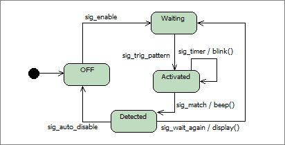
Simple Implementation of the State Machine
The simplest way of state machine implemetation is by nested switch-case instructions:

int sm_event_handler( struct * event_t ev ){
	switch( state ){
		case STATE_OFF:
			//handling event in OFF state
			switch( ev->signal ){
				case SIG_ENABLE:
					sm_transition( STATE_WAITING );
					return 0;
				}
			return -1;
		case STATE_ACTIVATED:
			//handling event in ACTIVATED state
			switch( ev->signal ){
				case SIG_TIMER:
					blink();
					return 0;
				case SIG_MATCH:
					beep();
					return 0;
		...

Above implementation is not very clean as is its effectiveness. It can be easily noticed that multiple times the state is tested (cases in external switch).

State Machine - Better Implementation
The issues with simple implemetation can be avoided by ordering numbers corresponding to symbolic state names (e.g. STATE_OFF, STATE_ACTIVATED etc.). For example:

typedef enum{ STATE_OFF=0, STATE_ACTIVATED, STATE_WAITING, STATE_DETECTED } state_t;

state_t state = STATE_OFF; //variable for current state, initialized to STATE_OFF

Above change provides a way to splitting one handler into multiple events handlers each for one state. Pointers to these functions can be put into a table:

typedef int (*sm_handler_t)( struct event_t * ev );//pointer to function 

//table of pointers
sm_handler_t handlers[]={ sm_handler_state_off, 
			  sm_handler_state_activated, 
			  sm_handler_state_waiting,
			  sm_handler_state_detected
			};

Now, instead of switch-case one need to call proper function from the table. It can be obtained by getting from the table the pointer to function pointed by current state.

int sm_event_handler( struct event_t* ev ){
//function call:
	return handlers[ state ](&ev);
}

//definition of single handler
static int sm_handler_state_off( struct event_t * ev )
{
	switch( ev->signal ){
		case SIG_ENABLE:
		sm_transition( STATE_WAITING );
		return 0;
	}
	return -1;
}
//consecutive handlers definitions follow
...

The simple means provided isolation of event handlers for each state. The source code is more clear and the executed is only the part of code that belongs to current state.

More State Machines
Above trick only illustrates some method, but does not show how to deal with:
- multiple instances of the state machine the same type,
- definition of state machines of different types,
Some proposition is presented here:
Implementation of state machines in DioneOS RTOS. Definition of the instances can be solved by using separated structures that contains all state machine data, the data that were global before that:

struct state_machine_t{
	sm_handler_t * handlers; //the table of handlers for the states
	int state;	//current state
	int states_nb;  //number of states
	void * xdata;	//some extra private data for state machine
}

Next, the structure should be passed as an argument to function-handlers and further to all operations on state machine. This description uses C language (if you use C++ it will be much simpler: instances are just objects of the class).

int sm_handler_state_off( struct state_machine_t * sm, struct event_t* ev )
{
	switch( ev->signal ){
		case SIG_ENABLE:
			sm_transition( sm, STATE_WAITING );
			return 0;
	return -1;	
}

Definition of Different Types of the Machines
When you want to define different types of state machines, you need to plan proper naming convention (namespace). You need to define states and signals for each type. You can consider usage of global signal naming (some enum) where each new type appends its signals. This implementation is consistent with solution, that uses signals (i.e. kinds of events) independent on state machines and are general set..

You can assume that each new type of state machine will be in separated source file with the name built on the type (this method is used in other programming languages - new class code is put in a file with the same name). The file contains all sources necessary for control the state machine.

Separation the Definition and Usage (Framework or Library)
The more you use state machines, the more attempting is an idea of some universal structure where user (programmer) does not need to implement general code for state machines but only defines its specific items (like states, signals, handlers, etc.) There are ready to use solutions (e.g. in
DioneOS system) that provides the framework that is some kind of template (pattern) of state machines. This can be formed by source files in C, preprocessor macrodefinitions and header files. Programmer defines specific type of the machine using this framework by definition only the handlers, events and the states. In order to use the machine of this type he just creates the instance of this state machine. One can notice levels of abstraction:
level type description notes
L1 META State Machine Framework provides code and methods for defining state machines
L2 TYPES Machine Type implementation of state machine of specific type
L3 INSTANCE Machine Instance usage, creation machine of specific type

State Machine Manager and State Machine as Active Object
State Machine implementation is not limited to providing the handlers for events. In order to use the machines effectively an infrastructure is needed for events transport, time scheuler for each machine and support for creation and destroying. Often some type of manager is used, that is responsible for these tasks. You need to be aware that most of solutions use Run To Completion method, this mean that the machine (its handler) works as long until it finish handling the event. In this period other machines are hold. In order to assure that no event will be lost queues are gathering not served yet events. When control returns to the manager and any event remains in the queues, the manager calls proper handler, for proper state machine. In this case blocking in handlers is not allowed (or not recommended). Refer to example
of the manager used in DioneOS system.

If pseudo-parallel execution is needed, multithreading can be used together with active objects:
- the manager can multithreaded and handle multiple (but not all) machines on each thread
- the state machine may have assigned its thread (active object implementation).
In those cases proper guarding the access to shared data must be implemented. It is recommended to communicate between machines only by events.

Code Generators and Translators
Last but not least, it is worth to mention code generators - programs that converts a model (e.g. in UML) into corresponding implementation. In this case all code of handlers, signal definitions, states etc are created automatically from the machine diagram drawn in graphic model editor. A programmer does not need to think about this implementation and should only to write a code of actions. Development of such generators is an experience of ELESOFTROM employee (refer below).

Linki

  1. StarUML - free software for drawing UML diagrams, including ones for state machines,
  2. The UML site, specification download etc.,
  3. "Translator of Hierarchical State Machine from UML Statechart to the Event Processor Pattern", MIXDES, 2007, str. 684-687, ISBN 83-922632-9-4,
  4. "New Pattern for Implementation of Hierarchical State Machines in the C Language, Optimized for Minimal Execution Time on Microcontrollers", MIXDES, 2008, str. 605-609, ISBN 83-922632-7-8,